Object
This post is to show you the way to configure VLANs on Ubiquiti Nanostation and demonstrate how to trunk the VLANs using over Point to Point Wireless. Ubiquiti Nanastations are very commonly used by customers when it is not feasible to connect two locations via fibre or the physical distance is over 100M for ethernet cables.
Environment
- Both the far and near ends are using Ubiquiti EdgeSwtich 10XP, I know it is definitely not enterprise enough.
- Both the far and near ends are using two Nanostation AC, again it is a small network setup, but the concept remains the same on the bigger units.
Switch Configuration
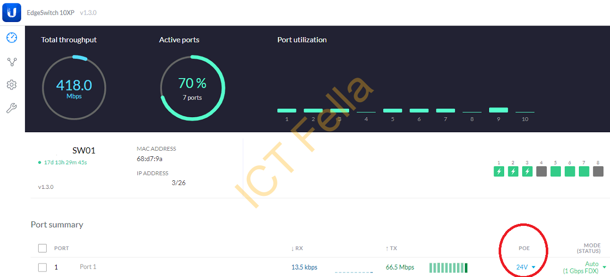
PoE is enabled on the Nanostation port to provide the power and data
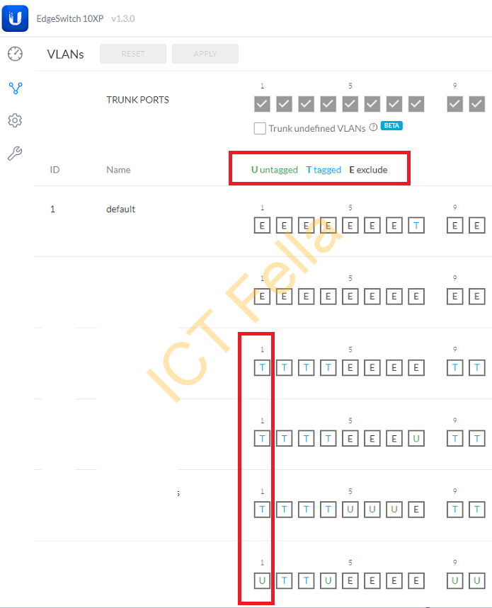
Switch port is configured as “untagged” on Nanostation MGMT VLAN and “tagged” on data VLANs that need trunking, with Cisco concept, native VLAN (untagged) is configured with MGMT subnet and Trunk port is enabled (tagged) for other VLANs that need to travel through this port.
NanoStation Configuration
In the Near End
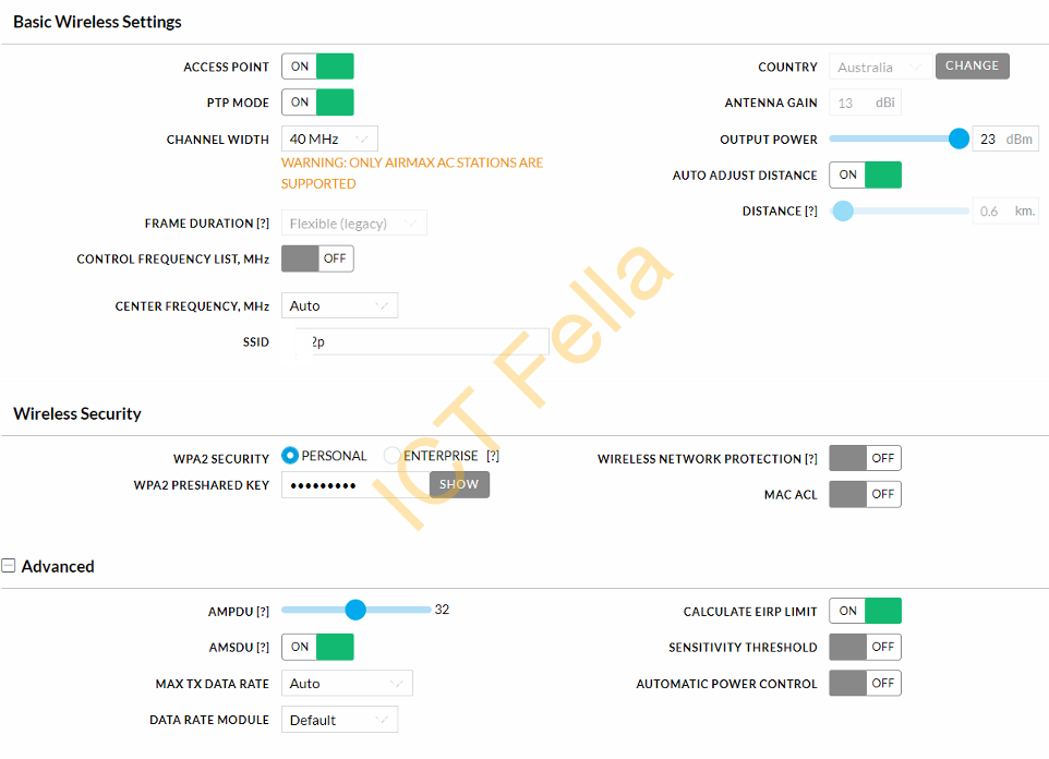
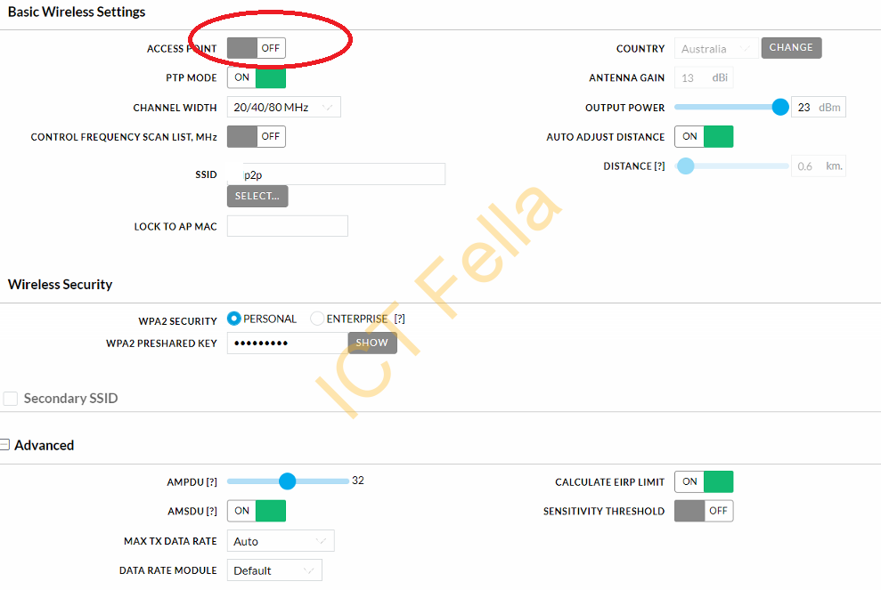
Please be aware of the configuration of the channel are manually configured on purpose.
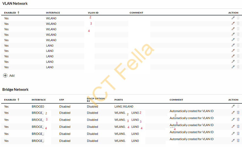
Please make sure you have WLAN, BRIDGE, and LAN interfaces for the VLAN you would like to “trunk”, in the example below, VLAN2, 3, and 4 are configured.
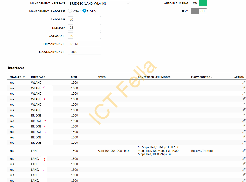
Then finally you “bridge” the WLAN0 and LAN0 interfaces
In the Far End
The only difference between the far and near the end is the Wilress and IP setting, the rest of configuring are the same.
Other Considerations
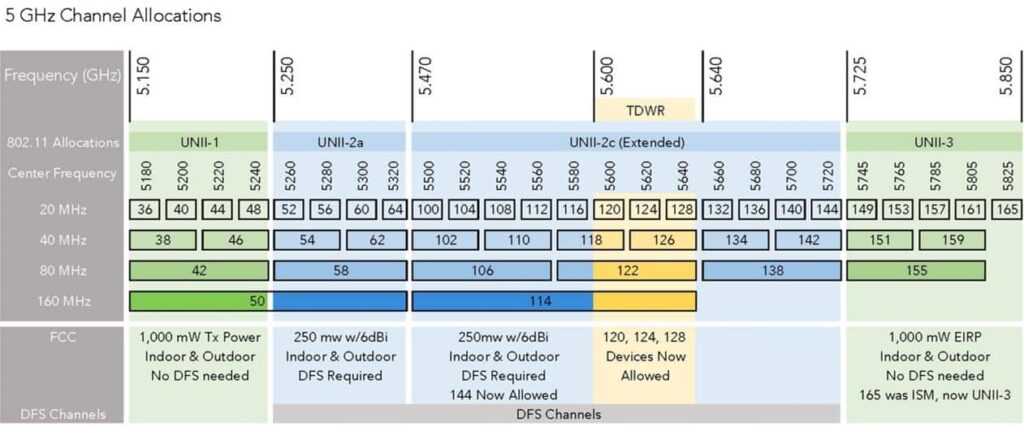
Don’t “overlap” on the existing channels with other wireless devices, here is a simple summary of 5GHz Channel Allocations.
Useful links
Intro to Networking – Introduction to Virtual LANs (VLANs) and Tagging
https://help.ui.com/hc/en-us/articles/222183968
airMAX – Management VLAN Examples
https://help.ui.com/hc/en-us/articles/204952204-airMAX-Management-VLAN-Examples